

|

|

|

|
WARNING: FOX Racing Shox highly recommends that a qualified bicycle technician install the 40 on your bicycle. Improperly installed forks are dangerous, and can cause loss of control and SERIOUS INJURY or DEATH. Read this page in its entirety before beginning the installation of your FOX 40.
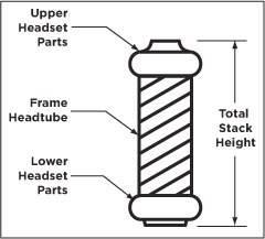
NOTE: The 40 direct mount crown requires a total stack height range from 105 mm to 166.8 mm.
See Figure 1: 40 Headset Stack Height to understand what defines total stack height. Measure to verify whether your total stack height falls within this height range specification.
NOTE: If you're installing a steerer tube-mounted stem, the total height of spacers used on a FOX steerer tube should never exceed 30 mm.
Figure 1: 40 Headset Stack Height

The 40 with a direct mount upper crown is assembled with the lower crown set to 163.7 mm below the top of the upper tubes (see Figure 2: 40 Crown Height). The lower crown position is set to allow 6 mm clearance between the bottom of the crown and the top of a 2.80" tire when bottomed out. Do not change the position of the lower crown.

WARNING: If the steerer has any nicks or gouges, the crown/steerer assembly must be replaced. A nick or gouge can cause the steerer to fail prematurely, which can cause loss of control of the bicycle resulting in SERIOUS INJURY OR DEATH.
NOTE: The FOX 40 can be set up with either a direct-mount or a steerer mounted stem.
CAUTION: FOX Racing Shox does not manufacture a direct mount stem. Be sure to refer to your stem manufacturer's installation instructions. Measure at least twice to be certain of all measurements, before cutting the fork steerer!
WARNING: Do not cut the steerer more than three (3) mm below the uppermost installed part. If the steerer length is mistakenly cut too short, it MUST BE REPLACED! Using a fork with clamped steerer engagement that is too short can lead to sudden fork failure, which can cause irrecoverable loss of control of the bicycle resulting in SERIOUS INJURY OR DEATH.
Figure 3: Star-fangled Nut Installation Depth

NOTE: It is important that the Direct Mount stem stays loose or uninstalled (NOT torque-tightened), to allow proper adjustment of the headset.
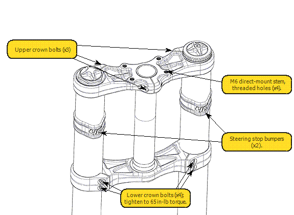
Figure 4: 40 Upper Crown Installation
  |
WARNING: Do not over-tighten the pinch bolts. Too much torque can damage the bolts, fracture the crown, or damage the threads. Any of these maladjustments could cause fork failure, leading to your loss of control and SERIOUS INJURY OR DEATH.
In the table below, all values assume that your tire is installed and fully inflated.
WARNING: For any fork model and size, do not use a tire if any of its measurement specifications exceeds its maximum safe value in the table below. Using tires with larger than these maximum safe values may cause you to lose control and suffer SERIOUS INJURY OR DEATH.

| Specifications | Fork Families | ||||||
| All 32 mm 26 inch |
All 32 mm 29 inch |
All 34 mm 26 inch |
All 34 mm 27.5 inch |
All 34 mm 29 inch |
All 36 mm 26 inch |
40 mm 26 inch |
|
| Maximum Tire Size | 26 x 2.40 | 29 x 2.30 | 26 x 2.40 | 27.5 x 2.40 | 29 x 2.55 | 26 x 2.80 | 26 x 2.80 |
| Maximum Peak Tire Diameter | 686 mm (27.00") | 744 mm (29.29") | 686 mm (27.00") | 716 mm (28.19") | 748 mm (29.45") | 694 mm (27.32") | 694 mm (27.30") |
| Maximum Edge Tire Diameter | 652 mm (25.67") | 721 mm (28.38") | 652 mm (25.67") | 690 mm (27.16") | 733 mm (28.85") | 670 mm (26.37") | 670 mm (26.40") |
| Maximum Tire Width | 61.0 mm (2.40") | 58.5 mm (2.30") | 61.0 mm (2.40") | 61.0 mm (2.40") | 60.6 mm (2.55") | 71.0 mm (2.80") | 71 mm (2.80") |

Refer to Figure 5: 40 Axle Clamps for the following procedure:
If installing a Steerer Mounted stem: tighten the steerer pinch bolts on the stem, according to the stem manufacturer's instructions.
Figure 6: 40 Upper Crown International 4-Bolt Pattern (Specification)

The 40 is designed only for use with DH disc brakes with disc rotor sizes of 200 – 225 mm. The 40 can use DH mechanical or hydraulic disc brake systems.
WARNING: Never modify the lower leg or use cantilever rim brakes, as this could lead to your loss of control, and SERIOUS INJURY OR DEATH.
The 40 disc bolt pattern uses:
|
Figure 7: 40 Brake Hose Guide Installation
|
Figure 8: 40 Disc Brake Hose Guide Routing
|
|
|

|
Bushing Technology & Inspection | Control Direction | Oil Volumes | Structural Inspection | Dropout Thickness Inspection | Torque Values | Unit Conversion | Suspension Tuning Tips | Using the Pump | Important Safety Information | Service Intervals | Contact FOX Service | Warranty Information | FOXHelp Service Web Site
Copyright © 2012
FOX Factory Inc.