


|
|
|
|
|
There are two basic styles of eyelet hardware: two piece reducer, and pin & sleeve. Click the photo that best matches your eyelet hardware setup.
|
|
Ideally, your shock reducers should always provide a snug fit for your rear shock on your bike. When excessive play develops in either a two piece reducer or pin and sleeve hardware assembly, this condition can worsen and lead to costly damage to your shock linkage. Eyelet hardware preventative maintenance with new DU bushings is always a good plan for helping prevent far costlier linkage issues.
TIP: Be sure that you have the correct reducer specification per make, model and model year of your bike frame.
"Extraction" | "Reducer Installation"
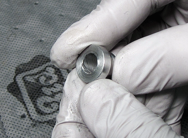
The two piece reducer hardware assembly comprises two reducer pieces, pressed into a DU bushing that is mounted in the shock eyelet.
Figure 1: Two Piece Reducer Assembly

Figure 2: Bolt Extractor
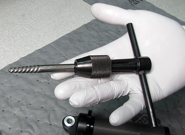
Figure 3: Reducer Piece Extraction Method
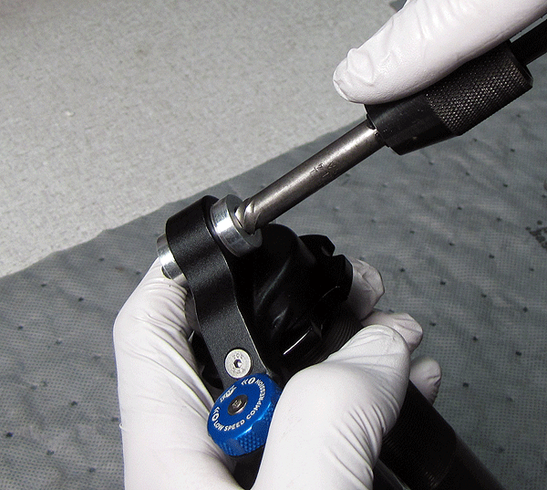
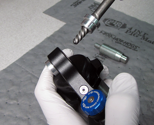
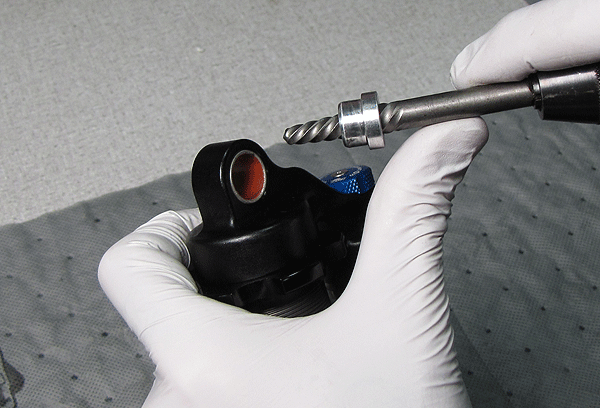
Figure 4: Reducer Piece Extraction Method, Repeated
TIP: Do not over-tighten the vise, to avoid crushing the reducer piece.
Figure 5: Freeing the Bolt Extractor from the Reducer Piece
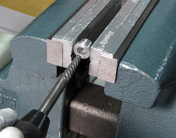
Figure 6: Bolt Extractor Impact
NOTE: Whenever you perform maintenance procedures on shock reducers, as a basic rule always replace the DU bushings. Removing a DU bushing is easily done with the two piece FOX DU Removal tool, PN 803-00-046-A.
Figure 1: DU Removal Tool, PN 803-00-046-A
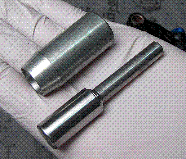
Figure 2: DU Removal Tool Parts
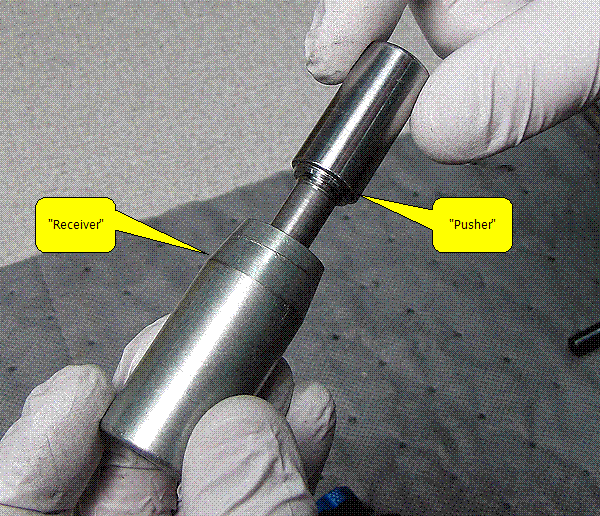
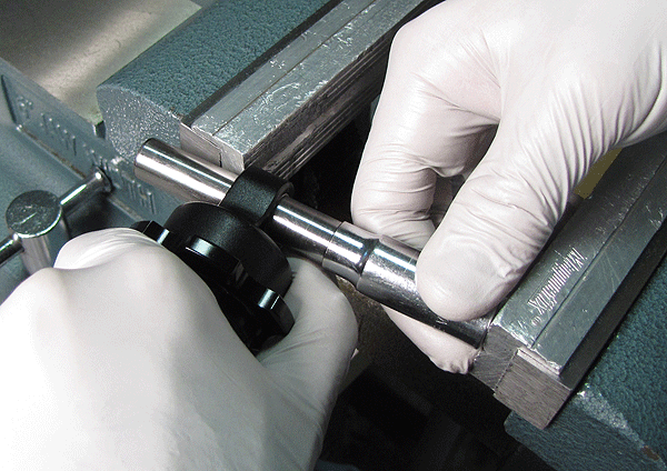
Figure 3: DU Tool Setup
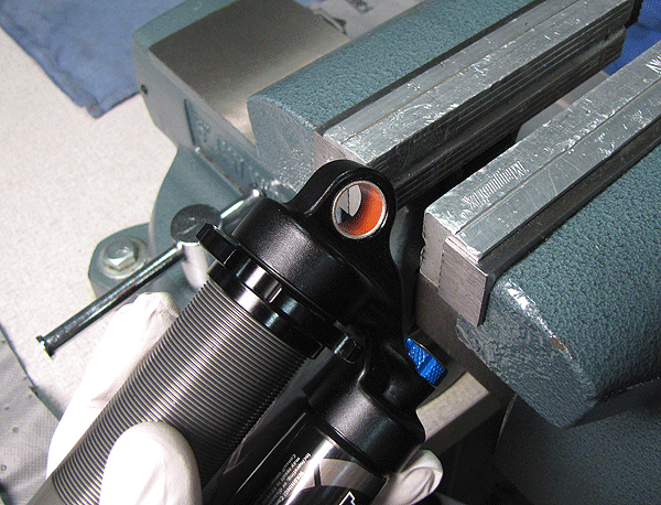
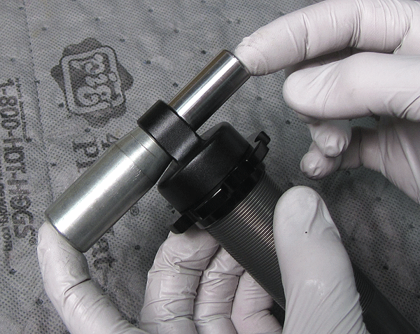
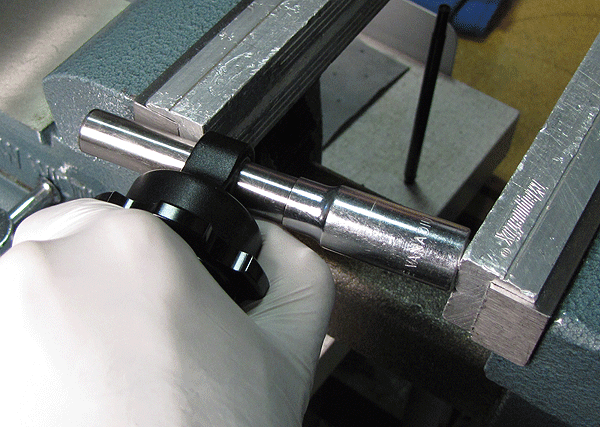
Figure 4: Compressing in the Vise
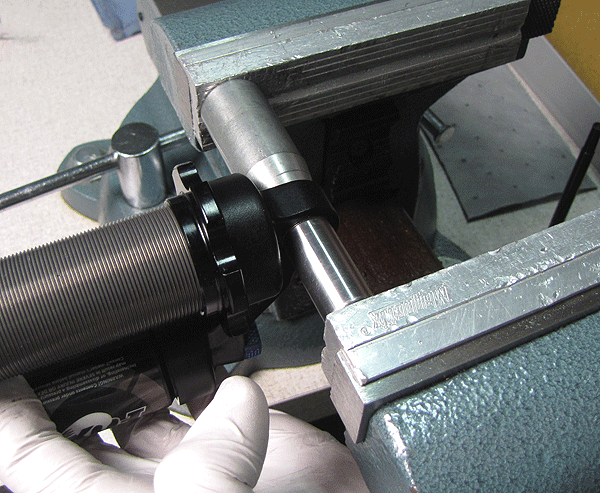
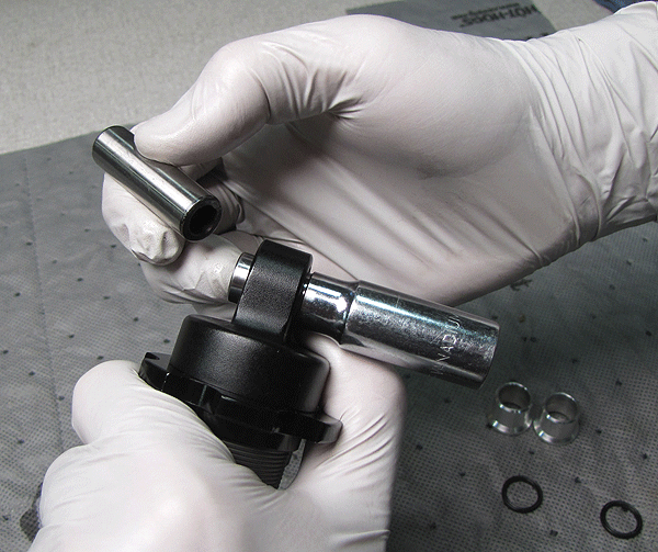
Figure 5: Worn DU in Tool Receiver
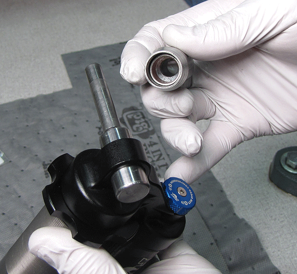
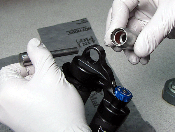
Figure 6: Installing a New DU Bushing
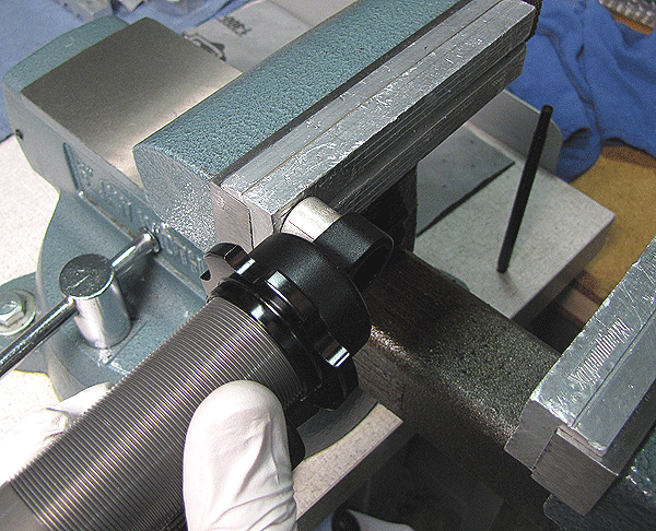
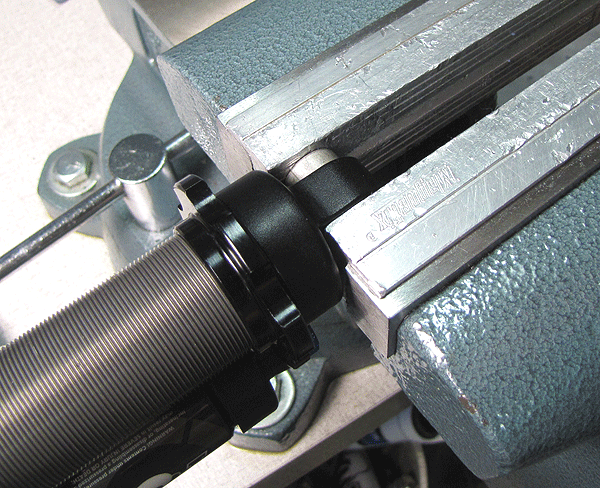
Figure 1: Installing the Reducer Pieces (1)
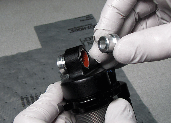
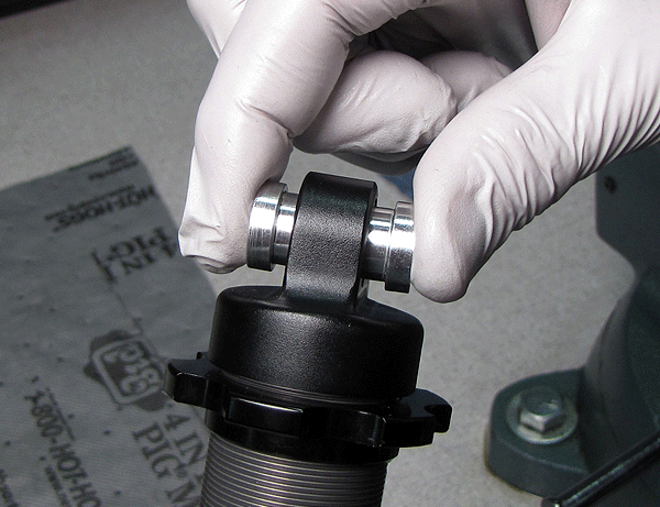
Figure 2: Installing the Reducer Pieces (2)
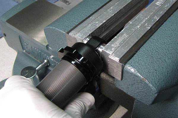
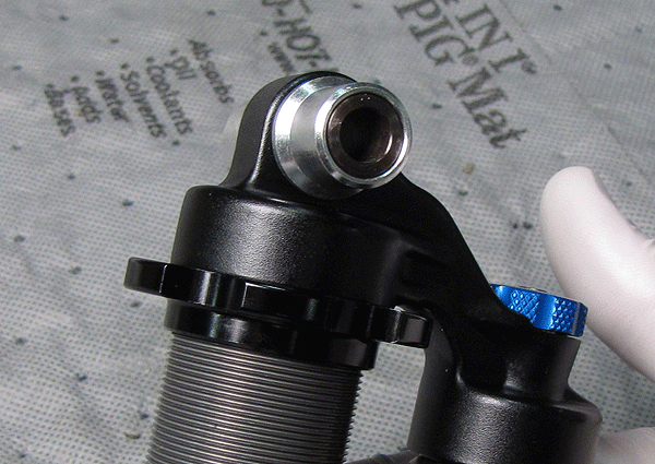
Figure 3: Reducer Maintenance Complete
"Disassembly" | "Installation"
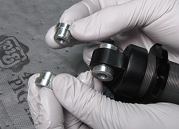
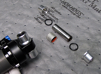
The parts shown below make up the pin & sleeve hardware assembly.
Figure 1: Pin & Sleeve Hardware Assembly
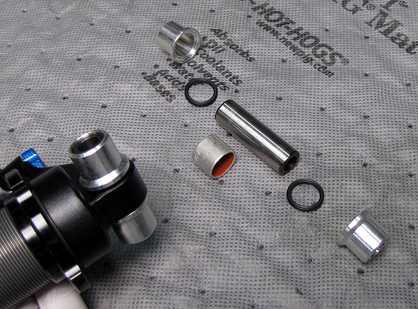
Figure 2: Removing the Sleeves
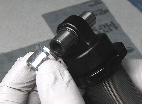
Figure 3: Removing the Rubber Rings
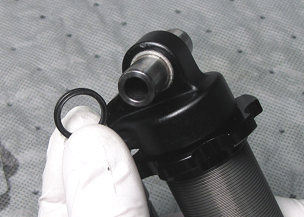
Figure 4: Removing the Pin (1)
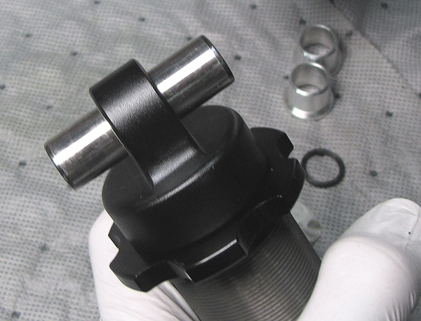
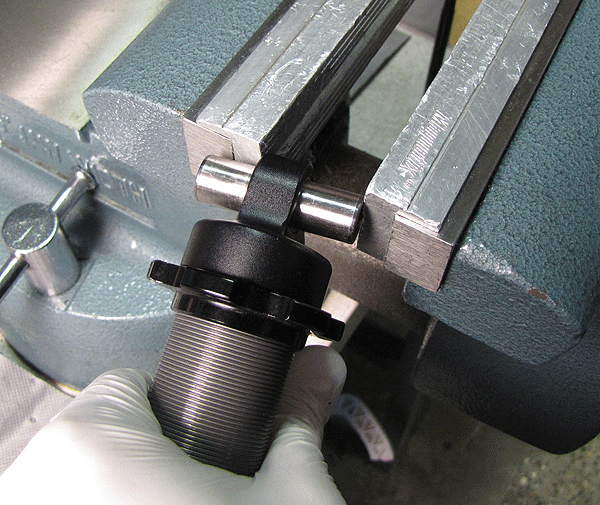
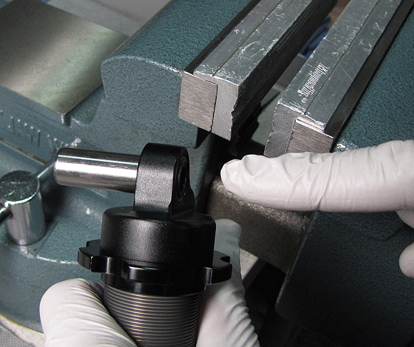
Figure 5: Removing the Pin (2)
NOTE: Whenever you perform maintenance procedures on pin & sleeve hardware, as a basic rule always replace the DU bushings. Removing a DU bushing is easily done with the two piece FOX DU Removal tool, PN 803-00-046-A.
Figure 1: DU Removal Tool, PN 803-00-046-A
Figure 2: DU Removal Tool Parts
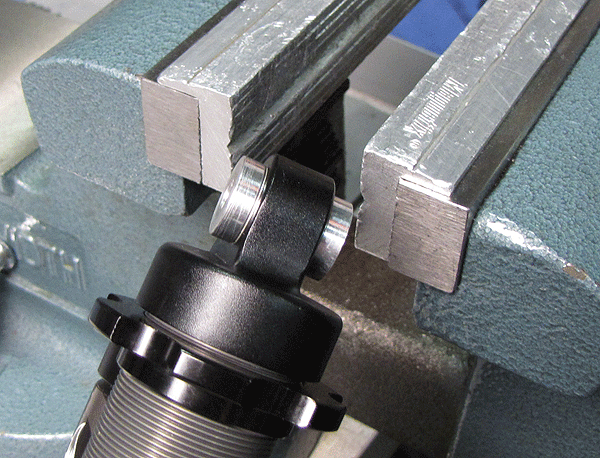
Figure 3: DU Tool Setup
Figure 4: Compressing in the Vise
Figure 5: Worn DU in Tool Receiver
Figure 6: Installing a New DU Bushing
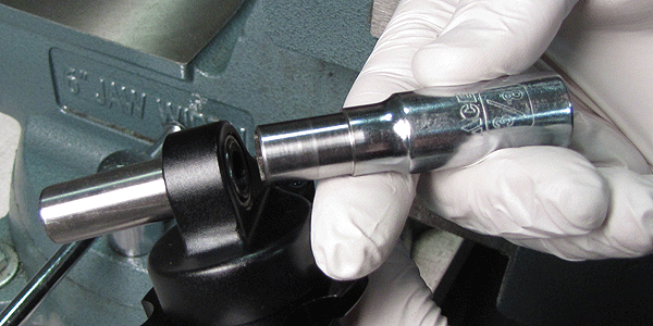
Figure 7: Starting the Pin
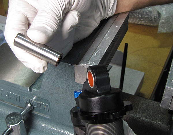
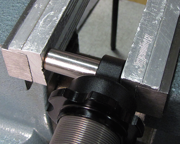
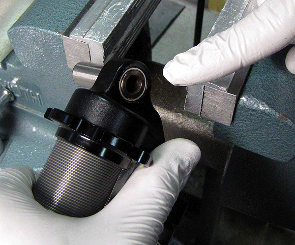
Figure 8: Centering the Pin (1)
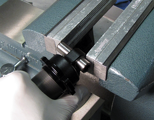
Figure 9: Centering the Pin (2)
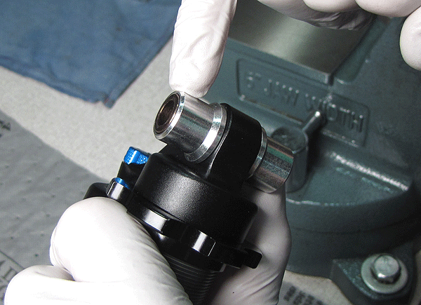
Figure 10: Installing the Rubber Rings
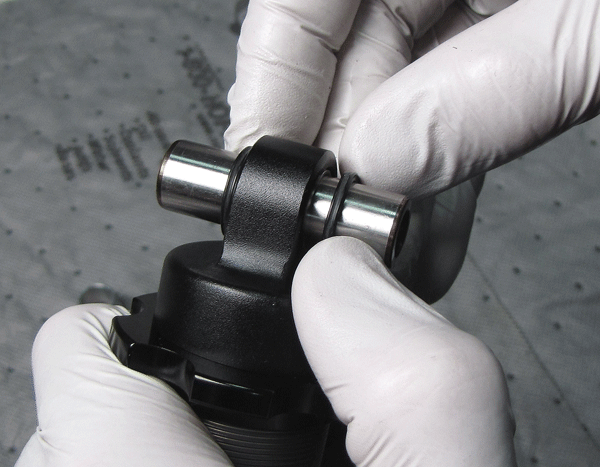
Figure 11: Installing the Sleeves
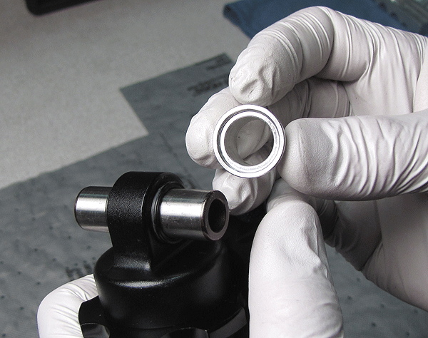
Figure 12: Pin & Sleeve Maintenance Complete
|
|
|
Bushing Technology & Inspection | Control Direction | Oil Volumes | Structural Inspection | Dropout Thickness Inspection | Torque Values | Unit Conversion | Suspension Tuning Tips | Using the Pump | Important Safety Information | Service Intervals | Contact FOX Service | Warranty Information | FOXHelp Service Web Site
Copyright © 2011
FOX Factory Inc.