You are here: Rear Shocks > Setting Up FLOAT Remote Shocks
Setting Up the FLOAT RL & RP2 Remote Shocks
NOTE: The FOX-Shimano Remote Lever is not compatible with the grip derailleur shifter system.
Figure 1: FLOAT Remote Rear Shock
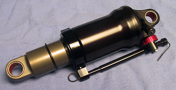
- After making certain that you have the correct shock size specific to your make of bicycle, mount your shock in the frame in accordance with the bicycle manufacturer's shock installation instructions.
WARNING: Rear shock setup and configuration varies greatly between different bicycle manufacturers. Be sure to refer to the owner’s manual for your bicycle brand. It is extremely advisable to have a qualified bicycle service technician install your new FOX rear shock on your bicycle. Improperly installed rear shocks can fail, causing the rider to lose control, resulting in SERIOUS INJURY OR DEATH.
- Mount the FOX-Shimano Remote Lever assembly on the handlebar:
- With a 3 mm hex key wrench, loosen the handlebar clamp bolt on the under side of the FOX-Shimano Remote Lever assembly.
- Remove the left or right hand grip from the handlebar, given which setup configuration you have.
NOTE: You may also need to reposition or remove the derailleur shifter.
- Slide the FOX-Shimano Remote Lever assembly onto the handlebar. Be sure 1) the lever release button is facing out towards the end of the handlebar, and 2) the cable adjusting barrel is pointing towards the center of the bike, above the hand brake lever assembly. This will be true for either left or right-hand setup configuration.
- Re-install the handlebar grip.
- Position the FOX-Shimano Remote Lever assembly closely to the inner end of the grip. Be sure the handlebar grip does not interfere with the normal operation of the lever release button.
- Push the actuation lever down to the activated position. Rotate the assembly, so the actuation lever in activated position does not interfere with normal thumb operation of your derailleur shifter.
- With a 3 mm hex key wrench, tighten the handlebar clamp bolt to seven (7) in-lb (0.80 Nm) torque.
CAUTION: Slightly decrease the tightening torque for carbon handlebars. Consult the bicycle or handlebar manufacturer’s documentation regarding the appropriate level of tightening torque for carbon handlebars.
- Press the lever release button, to ensure the FOX-Shimano Remote Lever assembly is released.
- Thread the barrel adjuster all the way clockwise in, then counter-clockwise back out a half turn.
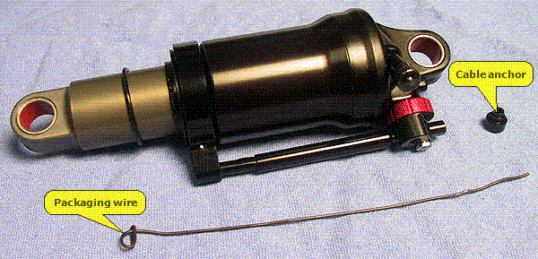
- Un-bend the end of the packaging wire (installed in the shipped shock; see Figure 1: FLOAT Remote Rear Shock) at the rebound adjuster end of the shock, and remove it. Don't lose the cable anchor that is temporarily secured with the packaging wire.
Figure 2: Remove Packaging Wire
- Determine which installation orientation of the remote cable housing you'll need to use (see Figure 3: Cable Housing Routing Option A and Figure 4: Cable Housing Routing Option B below).
Figure 3: Cable Housing Routing Option A 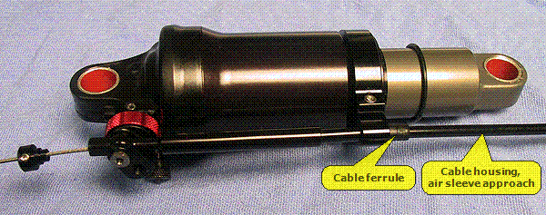 |
Figure 4: Cable Housing Routing Option B 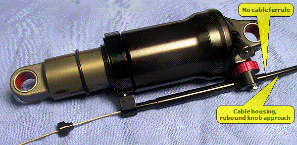 |
- Determine and cut the cable housing to proper length for the make and size of the bicycle. Use only 4 mm OD cable housing. Be sure that you install enough cable housing to provide 1) the necessary slack for proper shock operation throughout the entire shock stroke, and 2) enough handlebar steering rotation travel.
- If you choose to route your cable housing from the air sleeve end (see Figure 3: Cable Housing Routing Option A), use a cable housing ferrule with the cable housing stop in the shock. If your cable housing is routed from the rebound adjuster end (see Figure 4: Cable Housing Routing Option B), using a cable housing ferrule with the cable housing stop in the shock is not necessary. The housing stop located at the rebound adjuster end is sized to directly accept 4 mm OD cable housing.
- Regardless of which cable housing routing option chosen, slide the cable housing with inner cable into and through the lockout actuator mechanism. Pull the inner cable taught, making sure that both cable housing ends seat into the housing stops in the Shimano Remote Lockout lever and the shock itself.
NOTE: Be sure the barrel adjuster on the Shimano Remote Lockout lever is threaded all the way clockwise in, then counter-clockwise back out a half turn.
- Slide the cable anchor down the inner cable into the housing stop, holding it there while pulling the inner cable tight (see Figure 5: Securing Inner Cable, Option A or Figure 6: Securing Inner Cable, Option B below). Tighten the cable anchor screw to 7±1 in-lbs torque with a 1.5 mm Allen hex key wrench, to secure the inner cable.
Figure 5: Securing Inner Cable, Option A 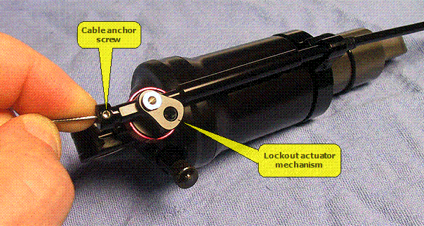 |
Figure 6: Securing Inner Cable, Option B 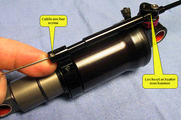 |
- Adjust the inner cable tension with the FOX-Shimano Remote Lever barrel adjuster, to achieve proper remote actuation adjustment (one to two turns counter-clockwise out, from full in).
NOTE: If the FOX-Shimano Remote Lever will not stay in activated position, the inner cable tension adjustment is too tight.
The actuator mechanism on the shock should be positioned as shown in Figure 7: Lockout or Propedal Not Activated when not activated (when the release button on the FOX-Shimano Remote Lever is pressed). Figure 8: Lockout or Propedal Activated shows the position of the actuator mechanism when lockout or Propedal® is engaged.
Figure 7: Lockout or Propedal Not Activated 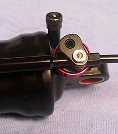 | Figure 8: Lockout or Propedal Activated 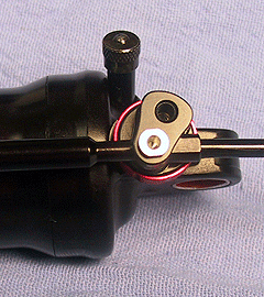 |
- Press the release button on the FOX-Shimano Remote Lever. Press down on the bike, to ensure the shock is in (and stays in) open position for either the Remote RL or Remote RP2 shock.
- Activate the FOX-Shimano Remote Lever. Press down on the bike, to ensure the shock is in (and stays in) locked out position for the Remote RL shock, or Propedal® position for the Remote RP2 shock.
- Trim the inner cable with cable cutters and cap it.
- Ride the bike in a controlled environment, testing for the normal operation of remote actuation and release.
Bushing
Technology & Inspection | Control
Direction | Oil Volumes | Structural
Inspection | Dropout Thickness Inspection | Torque Values | Unit
Conversion | Suspension Tuning Tips | Using
the Pump | Important Safety Information | Service Intervals | Contact FOX Service | Warranty Information | FOXHelp Service Web Site
Copyright © 2011
FOX Factory Inc.


