Installing the 36
WARNING: FOX Racing Shox highly recommends that a qualified bicycle technician
install the 36 on your bicycle. Improperly installed forks are dangerous,
and can cause loss of control and SERIOUS INJURY or DEATH. Read this
section in its entirety before beginning the installation of your FOX
36.
To install the FOX 36 fork on your bicycle:
- Remove the old fork from the bicycle.
- Remove the crown race from the old fork.
- Measure the steerer
tube length of the old fork. Transfer this measurement to your new
FOX fork's steerer tube.
Note: If there is no old fork to measure by, cut the steerer to the proper
length with the following procedure:
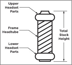
- Install the new fork on the bicycle using all of the headset parts. Use a
crown race setter to install the crown race firmly against the top of the crown.
- Install the headset spacers (these might not be required) and stem on the steerer,
and lightly tighten the stem clamp bolt(s).
- Mark the steerer tube with a scribe at the top edge of the stem.
- If it is necessary to cut the steerer tube, measure twice and cut once!
It is recommended that a cutting guide be used when cutting the steerer tube.
WARNING: If the steerer has any nicks or gouges, the crown/steerer/upper
tube assembly must be replaced. A nick or gouge can cause the steerer
to fail prematurely, and cause loss of control of the bicycle and SERIOUS INJURY or DEATH.
- Remove the new fork from the bicycle and cut the steerer tube ~4-10 mm below the scribed mark.
This ~4-10 mm of clearance allows room for the stem cap to lightly tension the headset,
to eliminate any free play. Refer to your stem manufacturer's instructions to be sure there will be enough clamping surface
for the stem.
- Use a flat file to de-burr the outer and inner top edges of the newly cut steerer tube.
- Install the star-fangled nut: with a star-fangled nut installation tool,
install the star-fangled nut into the steerer to the proper depth (see the star-fangled nut installation depth drawing below).
CAUTION: The total height of spacers used on a FOX steerer tube
should never exceed 30 mm.
- Using a
crown race setter to install the crown race firmly against the top of the crown.
- Install all headset parts and stem spacers (if these spacers are required).
- Torque the star-fangled nut to the stem manufacturer's specifications, and also torque the stem clamping bolt(s) to specification at this time.
- The headset should be so well adjusted that it turns
freely without drag or free play.
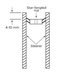 Star-fangled nut installation
depth
Star-fangled nut installation
depth
Tire Sizes
The 36 will accept tire sizes up to 2.80 inches wide. Any tire larger
than 26 x 2.60 must be checked for clearance using the following method.
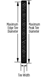
Determining correct tire size
With the tire installed and inflated on the rim, measure the following three dimensions:
Maximum Peak Tire Diameter
= 694 mm = 27.3 inch
Maximum Edge Tire Diameter
= 670 mm = 26.41 inch
Maximum Tire Width = 71
mm = 2.80 inch
WARNING: Do not use a tire if any measurement exceeds the maximum
dimensions shown above. Using larger tires is not recommended and can cause SERIOUS INJURY or DEATH.
- See Using the Quick Release Lever.
- Setting handlebars straight and torquing
stem bolts:
- Set
the bike on the ground and sit on your bike to set the handlebars straight
relative to the front wheel.
- Tighten
the stem pinch bolts and torque fasteners according to the stem manufacturer's
specifications.
- Check
that the handlebar pinch bolts are tightened to the stem manufacturer's torque
specifications.
Post Mount Disc Brake Installation
CAUTION: IMPORTANT: the disc brake caliper mounting bolts must have 10-12 mm of thread engagement with the fork.
Be sure these mounting bolts are torque wrench-tightened to the manufacturer’s specification. In any case, the disc brake caliper
mounting bolt tightening torque level must never exceed 90 in-lb (≯90 in-lb).

Note: The 36 is designed for use with disc brakes with disc rotor sizes of 160 – 205 mm only. The
36 can use XC or DH mechanical or hydraulic brake systems.
WARNING: Never modify the lower leg, or use cantilever rim brakes. Doing so may lead to SERIOUS INJURY or DEATH.
The 36 disc bolt pattern uses:
For use with XC size rotor (160 – 180
mm outside diameter):
- XC caliper
- XC caliper mount for international
XC mount pattern
OR
For use with DH size rotor (200 – 205
mm outside diameter):
- XC caliper
- Install DH disc brake system according to disc brake manufacturer's specifications.
Be sure to torque all fasteners and bolts to manufacturer's recommendations.
- Consult the manual that came with your disc brakes for proper installation procedures.
It is recommended that NEW disc brake pads be installed to ensure proper
alignment and to minimize drag.
- Test brakes for proper operation on level ground before hitting the trails.
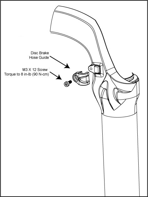
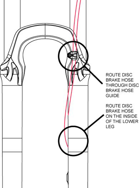
- Route the
disc brake hose (for hydraulic disc brakes) or brake cable housing (for
mechanical disc brakes) from the caliper to the inside of the lower leg
and through the supplied disc brake hose guide, and assemble the FOX disc
brake hose guide parts as shown in the figures below.
- Cut your Brake hose or brake cable housing to the correct length and assemble according
to disc brake manufacturer's specifications.
- Tighten the disc brake hose guide screw with a 2.5 mm-hex key wrench and torque
to 8 in-lb (0.90 Nm).
Bushing
Technology & Inspection | Seals & Foam
Rings | Control
Direction | Oil Volumes | Structural
Inspection | Dropout Thickness Inspection | Torque Values | Unit
Conversion | Suspension Tuning Tips | Using
the Pump | Important Safety Information | Service Intervals | Contact FOX Service | Warranty Information | FOXHelp Service Web Site
Copyright © 2011
FOX Factory Inc.